Professional Drones and UAV Solutions

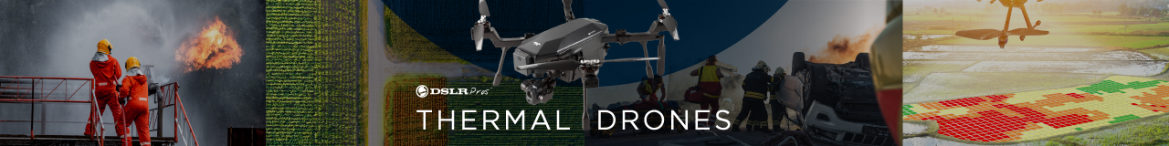
DSLRPros has been assisting police, fire departments, search and rescue teams, agriculture and industrial inspectors, and education institutions in launching and equipping their own drone programs since 2012.
From identifying crop stress to finding missing persons, we know the potent efficiency of unmanned aerial systems (UAS). No wonder we are the go-to drone shop of organizations looking to harness the power of professional drones.
Contact our drone specialists today for assistance: (213) 262-9436 or Sales@DSLRPros.com.
Se Habla Español
FREE SHIPPING ON ORDERS OVER $199!


DSLRPros is an authorized DJI Enterprise, FLIR thermal, and senseFly master distributor. We provide professional drone packages and trainings for police, search and rescue, commercial inspection, agriculture, and security organizations.
We combine the best flying platforms, camera payloads, software, and accessories for a ready-to-go drone solution right out of the box. Give us a call at (877) 299-1075 to learn how we can help jumpstart your organization’s drone fleet!